Cabrillo College Planetarium
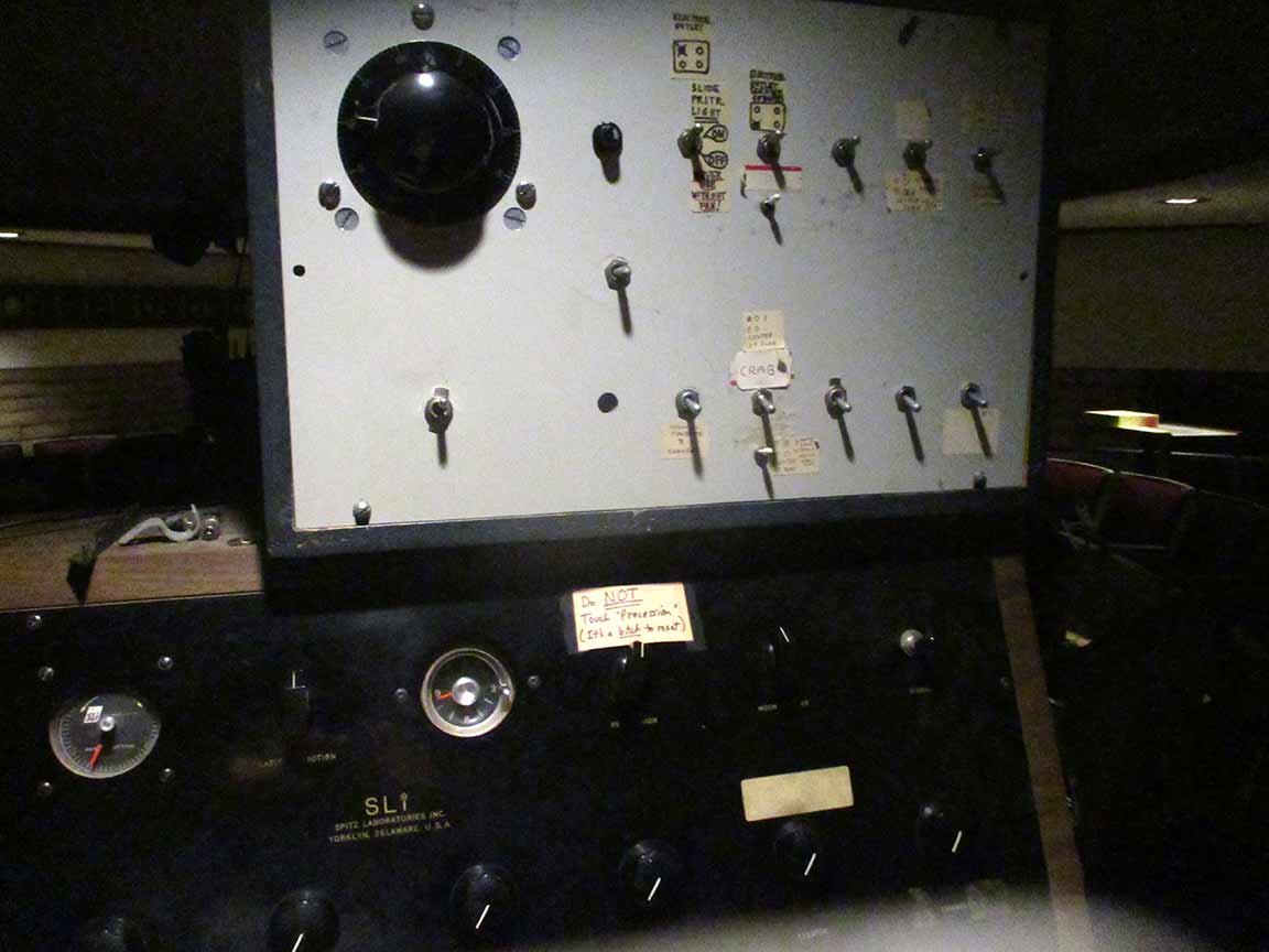
Diagnosing the troubles - Summer '22
Related: Star Ball power troubles in 2016
I ran some tests and took photos on June 27. Comments below.
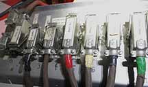
1a. Soldered connections all looked fine. |
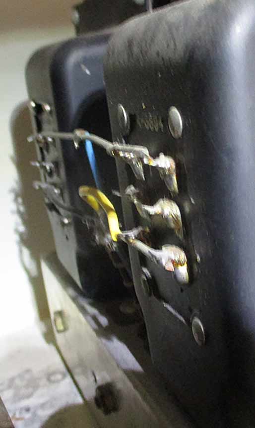
2a. Soldered connections looked fine |
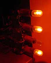
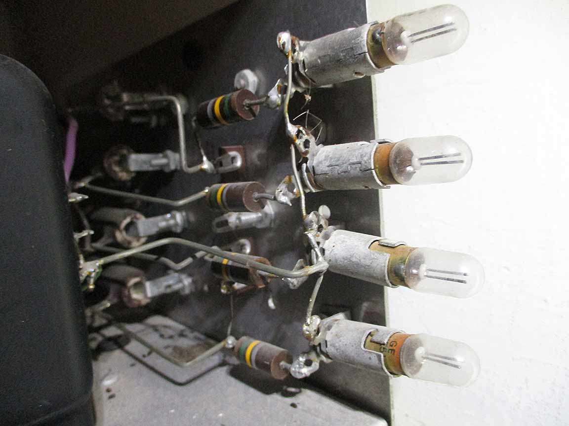
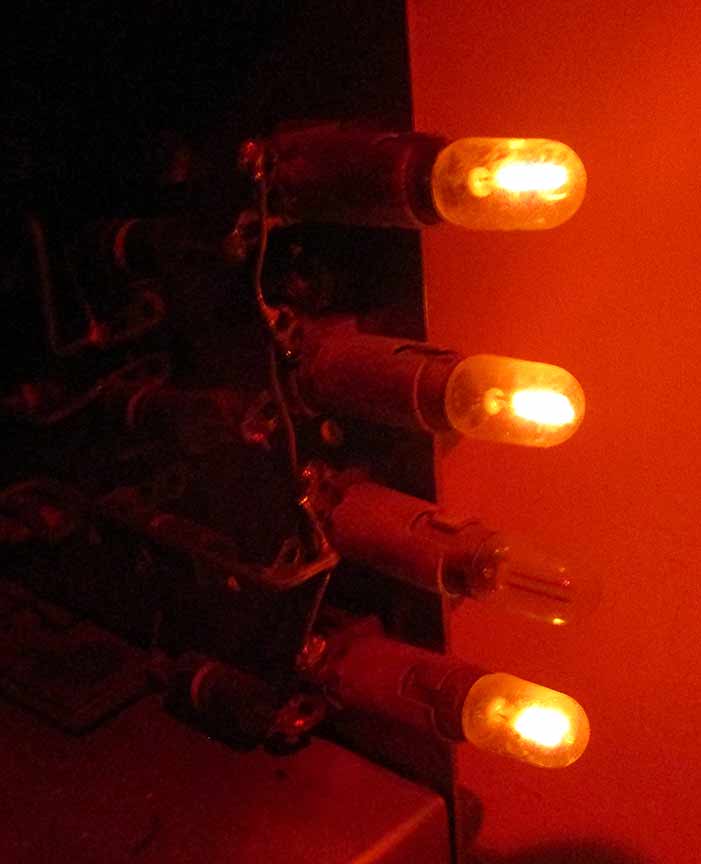
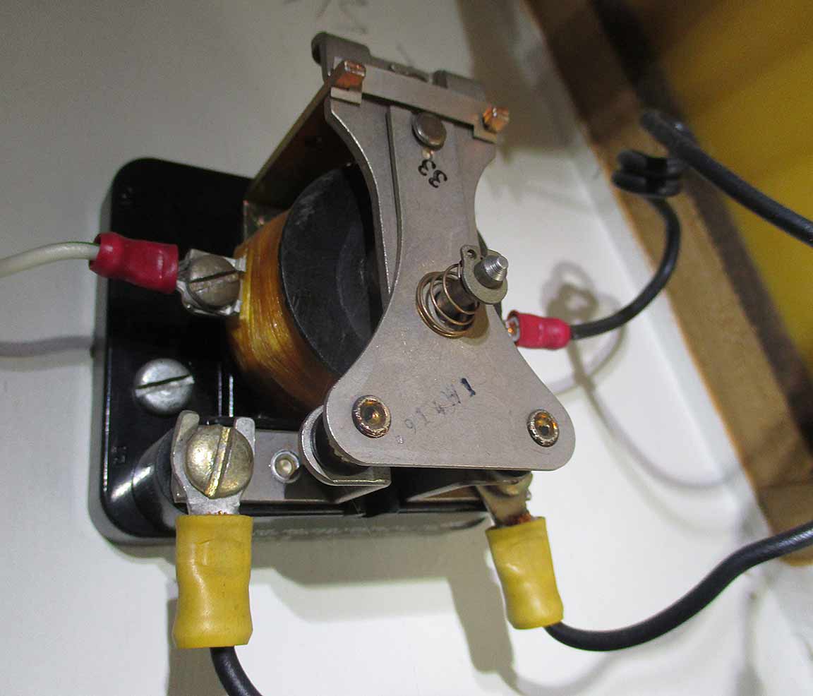
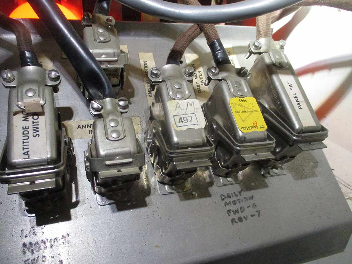
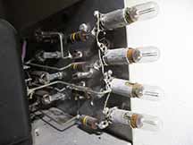
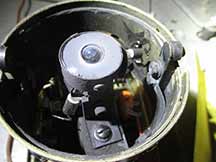
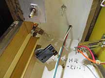
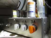
3a. Annual motion box, this is how the lights were lit. I moved the light bulbs and this pattern did not change. The light bulbs are fine, it must be inside the annual motion box that there's something wrong causing the light to not glow. |
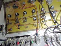
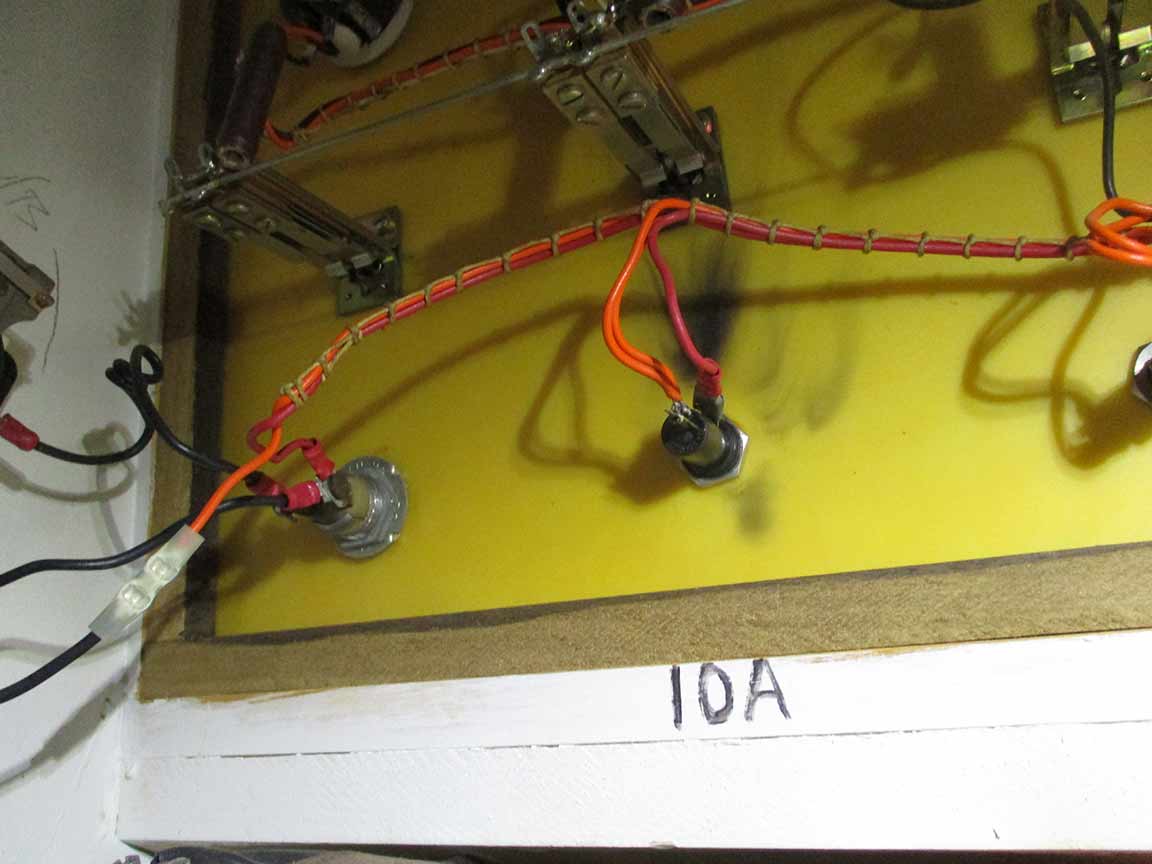
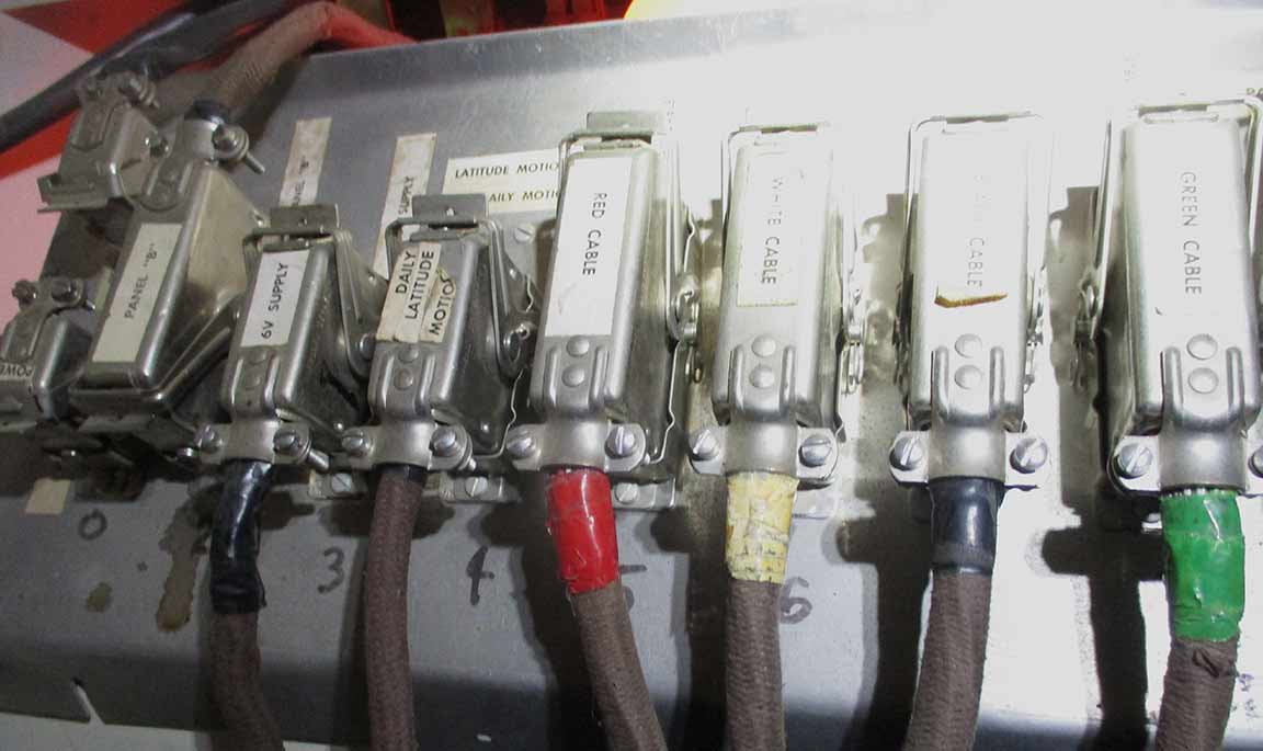
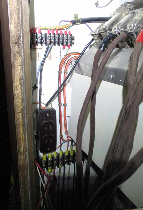
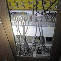
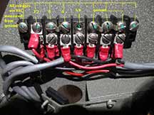
4a. connections all looked OK. No voltage mesaurements taken, however. The large connectors e.g. seen along the bottom of this picture, were all checked to be snug |
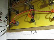
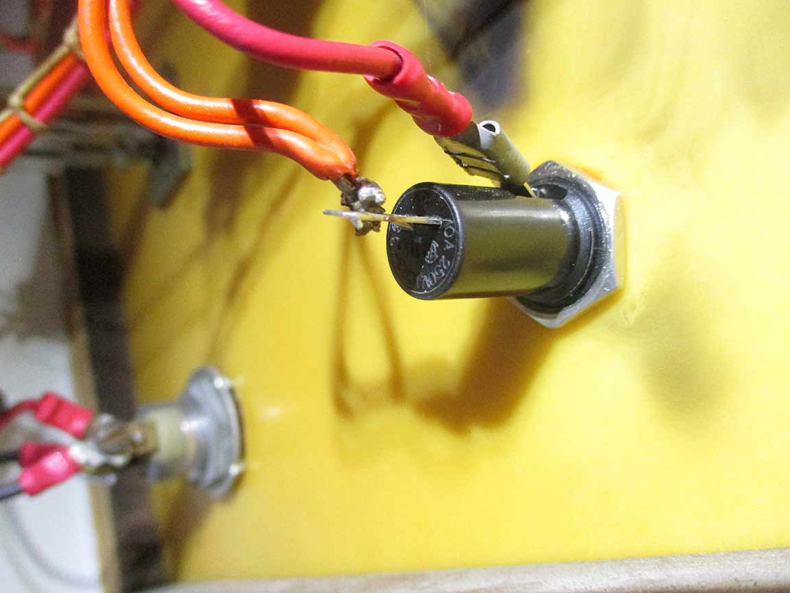
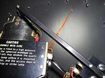
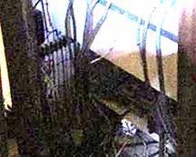
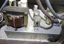
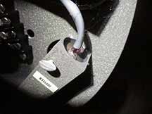
5a. No new damage seen here. The burn mark is from 2016 and fuse and holder were replaced at that time. But the connection between wire and fuse-holder lead is weak. |
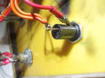
6a. Main power fuse, was not blown. But, the connection to the wire was flakey. In trying to remove the fuse to examine it, the twisting caused the wire to lose contact with the fuse holder. This fuse blew in 2016 and was replaced at that time. See that story... |
7a. A photo through the port into the star ball while lamp installed. Nothing unusual seen |
8a. The replacement lamp, re-installed in the star ball. Looked fine upon unpacking, and after installation and attempted power up. |

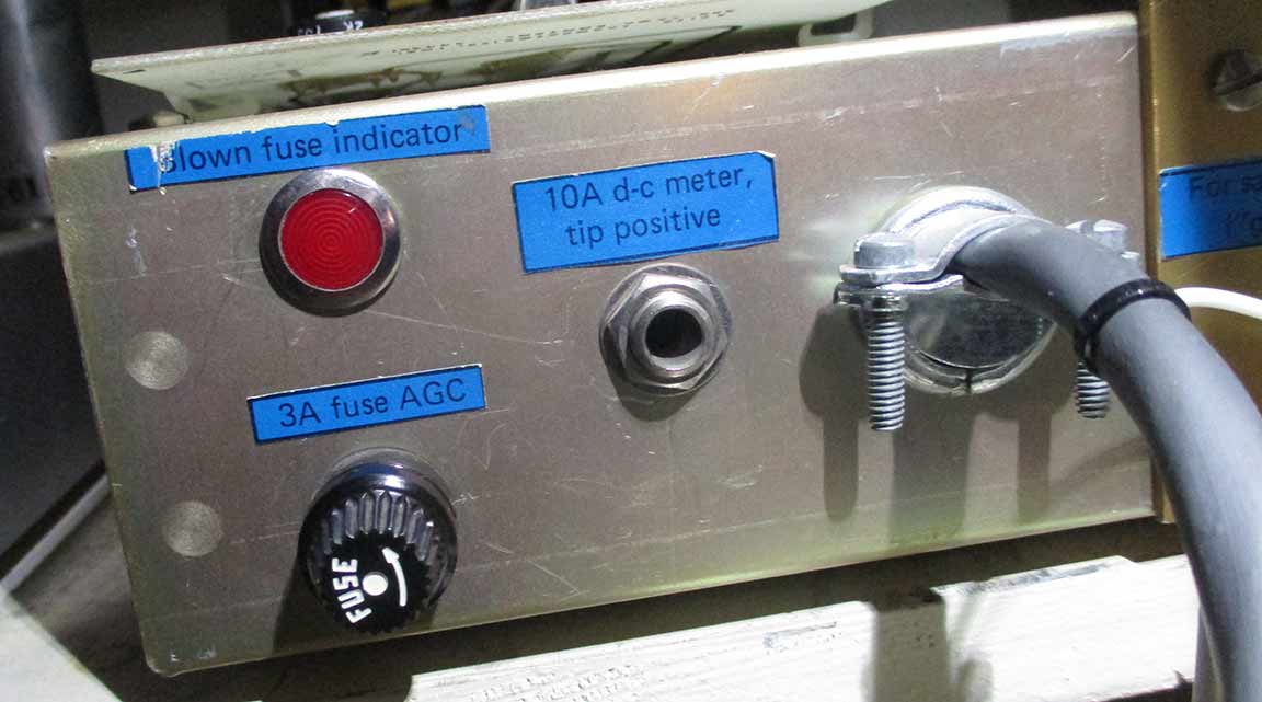
9a. I removed and examined this fuse. It was fine, and the red light above lit, properly, when the fuse was removed. |
10a. no damage obvious here either |

11a. Connections looked normal |

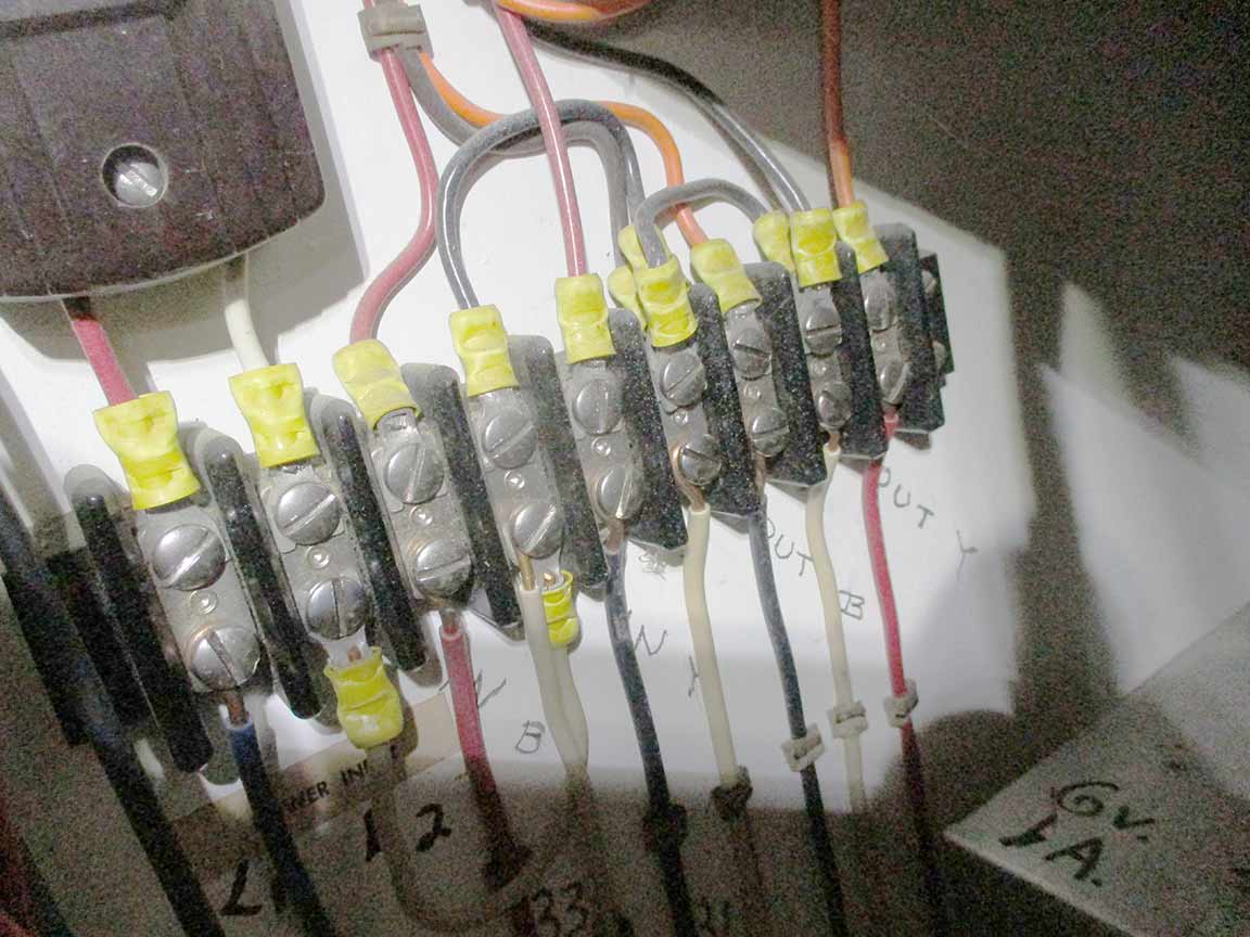
12a. Connections looked normal. These are all on the wall of the console, not on any electronics unit box. |
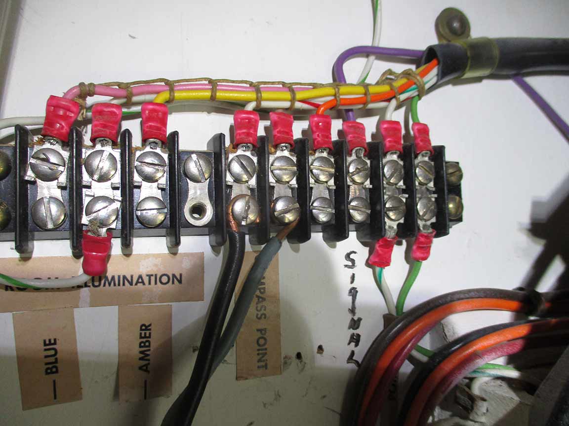
13a. Connections looked normal |

14a. This lumline does not light when the front panel knob "Panel lights" rheostat is turned on. Dead bulb, perhaps? I don't know if we have a replacement. |
15a. Connections looked normal |

16a. Connections looked normal and checked to be snug. |
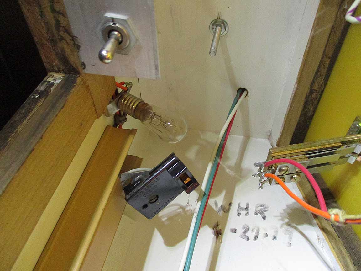
17a. The upper left side inside the back of the console. Looks like a bulb or two should be here, but wasn't. I flipped the toggle switch on and off, and saw no effect. |
|
|
|
Tests Done June 27
1. Tested DC voltage across star ball arms, after turning on the power and turning on "stars". There was zero voltage and zero amps. No power is going to the star ball.
2. I checked the orange light bulbs on the box inside the back of the console's "annual motion", switching their positions and always it was the 3rd position that was dead. The fault is not a blown light bulb, but the power to the light bulb is the problem or upsteam of that.
3. Twisting the "Main Power" fuse container from the front side of the console, caused the fuse holder to rotate as it's stiff and insufficiently clamped by the rearside thin nut. That twisting causes the main power to come on or go off as the power fails to cross the fuse. It should be re-soldered (we can do that, here). However, even when it makes electrical contact, we still get no power to the star ball.
Power Issues:
* We get power to the motor running daily motion, but it squeeks when operating. It looks like it was left on for days sometime in the recent past.
* We don't get any power to the star ball, nor to the motors running the planets, sun, or moon? At least, running annual motion I hear the usual sounds but I see nothing on the ceiling. Nor do I see the mirrors rotating.
* When I first came in a few weeks ago and checked it, turning on the main key I could see the twilight glow. But after powering off and then on, that light no longer operates. There seems to be failed power to many parts of the projector assembly, but daily motion does still happen.
================================================================================
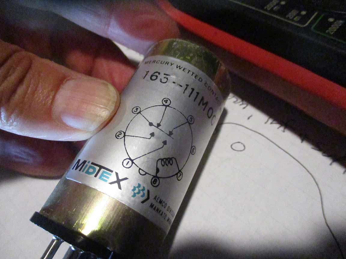
June 29: Here's a photo from Eric at Ash, asking to test these, as shown in image. Eric's instructions in email...
Have you had Tom Trumbull back in to check the stars out? It sounds like he did a great diagnosis the last time. If you have nothing going to the star lamp, I would suspect the 2n3442 transistor on the power supply heat sink, or on the plug in card. Those are the only real “active” components of the system, and do go out from time to time.
Have you tried plugging a 1/4” plug into the jack next to the fuse on the star lamp supply and seeing what kind of current reading you get there?
I don’t understand "Can you tell me which image corresponds to the one you want me to test voltages to, with the gold?"
There are 2 power supplies (chassis) related to annual motion. One of them is typically labeled “speed” the other “transformer”. You’ve sent several pix of the transformer chassis, but none of the speed chassis. It’s very rare that anything goes wrong with the transformer chassis. The speed chassis is where the 2 gold relays are that need to carefully be swapped to see if the problem lamp socket on the transformer chassis moves from #3 to probably #1.
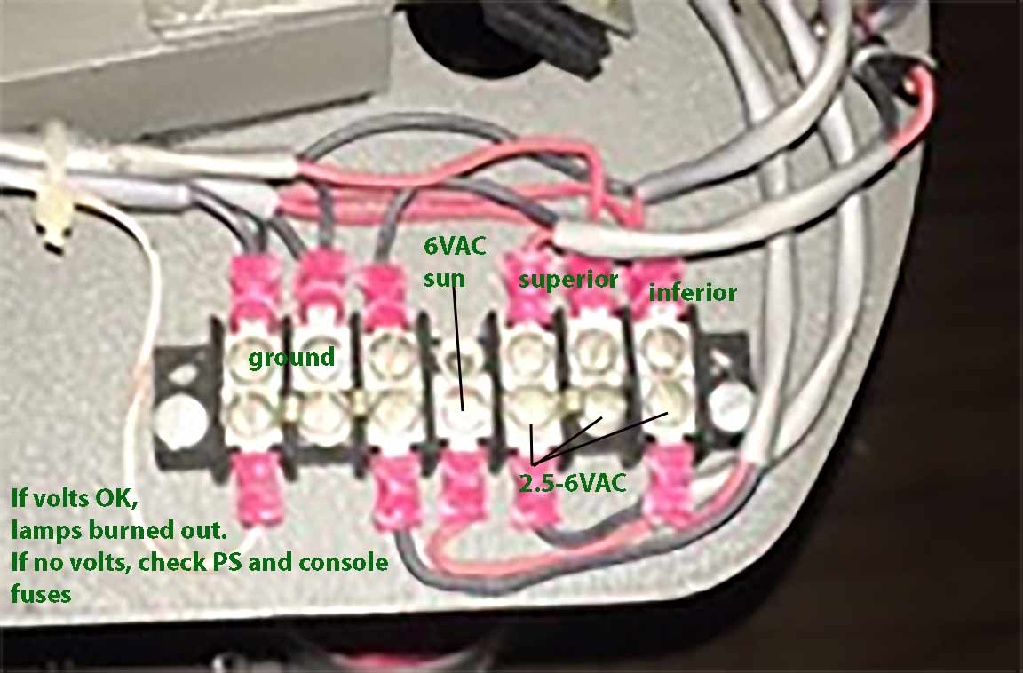
The only other voltage check is on the small barrier strip I sent a pic of yesterday for the sun & planets. (below)

18a - Image from test setup A3P at Ash Enterprises, sent by Eric. "Barrier strip" |
Here's the results of my Planetarium work today...
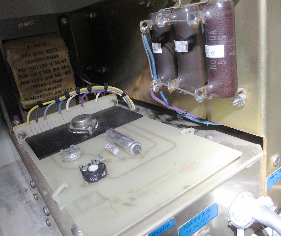
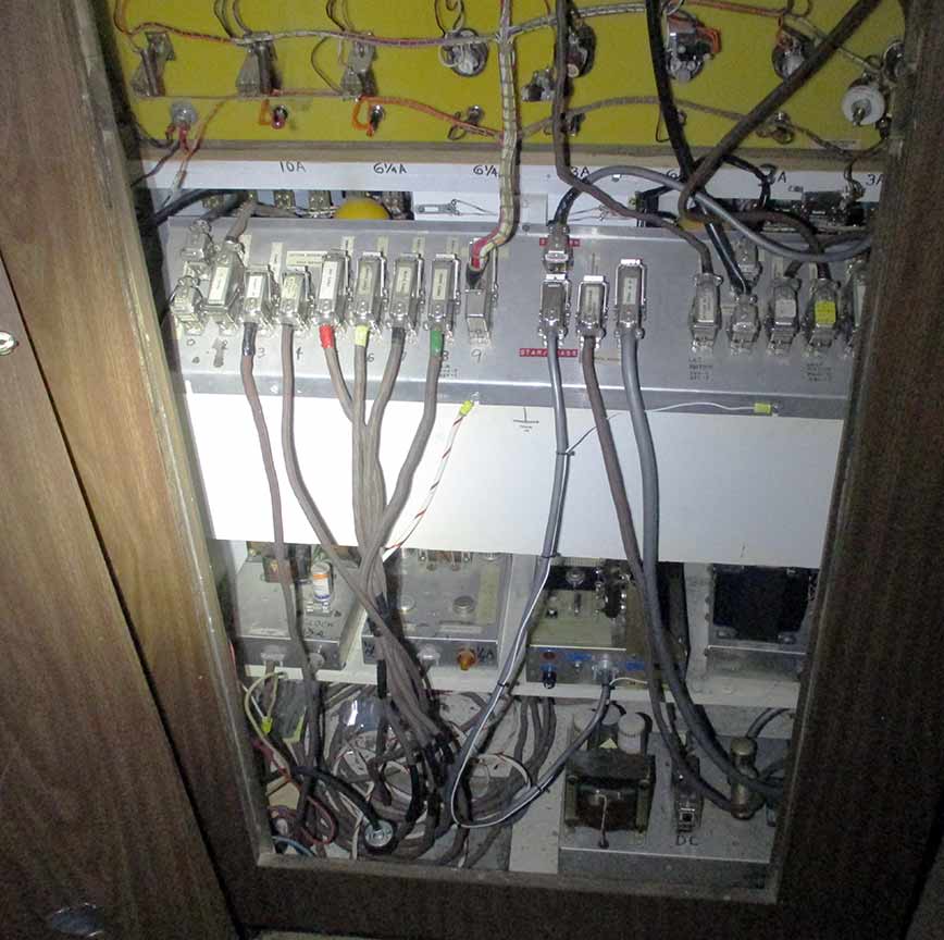
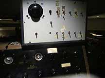
1b. This shows all the electronics.If there's a control box that's not here, we don't have it.
top shelf from left:
6V power supply for all lamps except Stars.
Latitude and daily motion power supply
Star lamp power supply
Annual motion transformer chassis
Bottom shelf, on the right side:
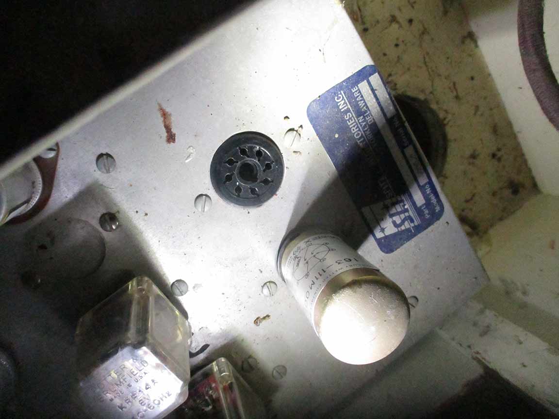
Annual motion speed chassis, which has the gold cans (1" tall, 2.5" diameter). Be very careful not to break off the center registration pin. Swap them and see if the 3rd lamp which is currently not lighting up, becomes now the 1st lamp which is off. |
This is the lower left corner of the same area, but shot in 2016. I wanted to see if that plug was hanging free back in 2016 too, but it's too hard to tell in this photo. My worry - did this plug go to a "110 power supply in console" that is now missing? Stolen?? |
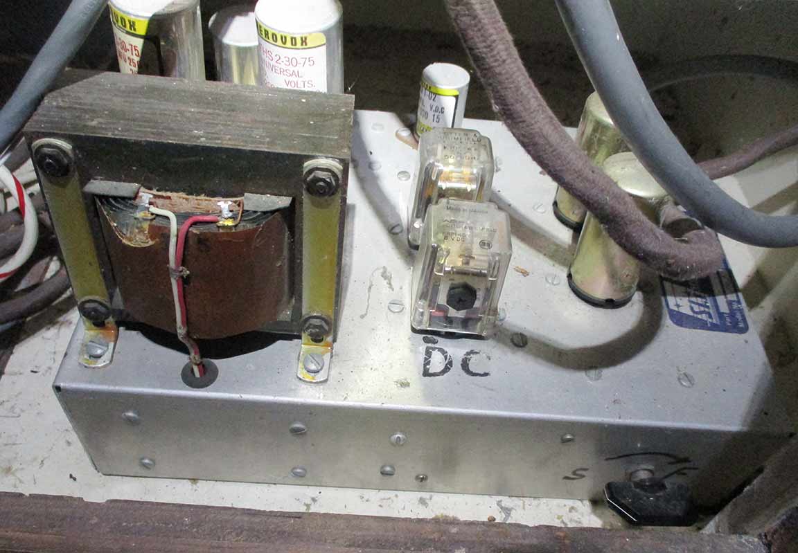
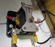
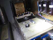
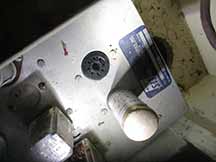
2b. This is the annual motion speed chassis, on the bottom shelf. Looked normal upon inspection. The knob at lower right is labelled "S" to "F", (slow to fast?). I have not touched that setting.
The gold cans Eric refers to look to be the two cans on the right side of the box top. Try very carefull removing them and swapping them to see if the orange lights which are on, change
|
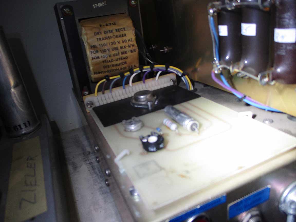
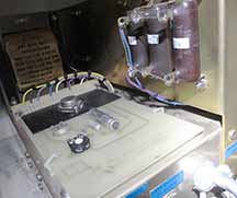
3b. Surface board on the box that has the plug for checking amps. I need to locate a proper male plug to do the amperage testing suggested. The surface components looked normal. No evidence of burnt component. |
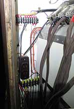
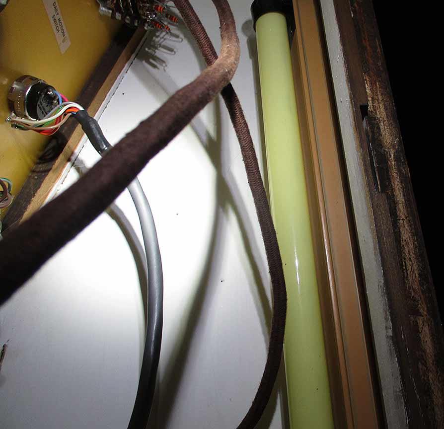
4b. The left side inner wall has these junction lines. There's nothing similar on the right side. |
5b. Looked normal as well |
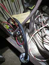
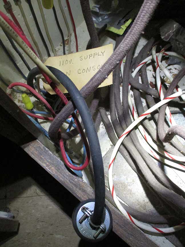
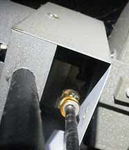
6b. This cord is puzzling. It has long had a tag, seen here, but there is nothing plugged in to the male 2-prong plug at the bottom of this photo. |
7b. I checked these 3 fuses, on the back side of one of the electronics boxes. The fuses were all good. |

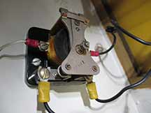
8b. Associated with the "Stars" on the console. Looked normal. |
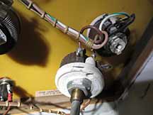
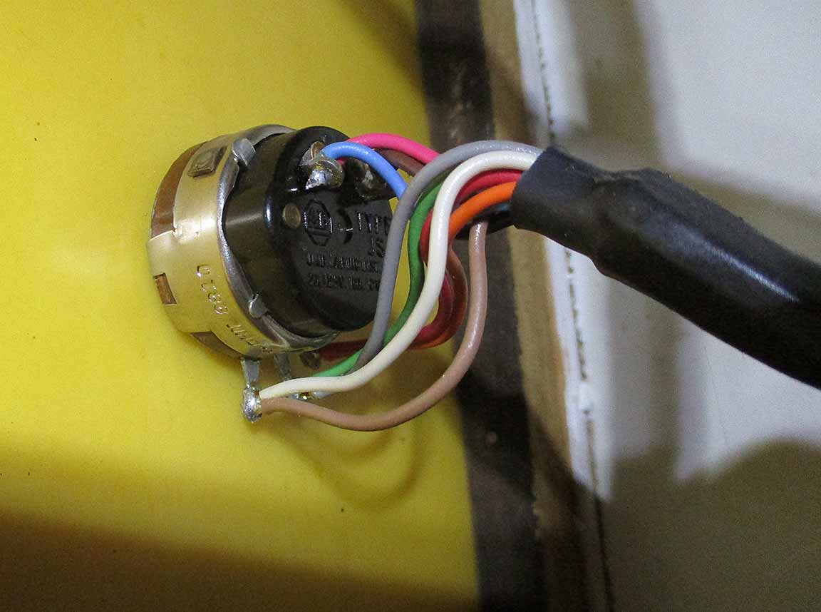
9b. Also associated with the Stars, There's this peculiar rheostat control hanging off of it. Connections looked good and no evidence of trouble. |
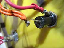
10b. The main power fuse. In tightening the nut seen on the fuse holder, the solder joint, which was already hanging by a threat of wire or solder, separated. At this point, I went to the Observatory 3/4 mile away to get a soldering iron and solder. I did not return in time to do the sodering and any powered testing of voltages anywhere - I'd have had to be biking home after dark. |

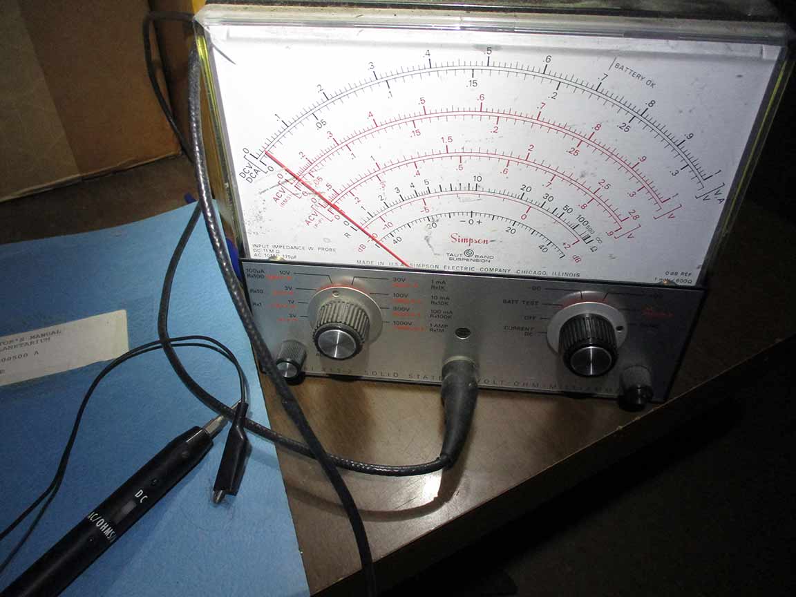
11b. In addition to my new small handheld multimeter, there is this classic old one we've had at the planetarium forever. The probe connects with a BNC, and the probe end does not have the 1/4" jack which would apparently be necessary to check the amps suggested by Eric, and seen in Image 9a. |
* Next visit I will solder the main power fuse wire back onto the holder lead.
* I cannot check the suggested voltages on the "small barrier strip" until I locate where that strip is. So far, I cannot find it. The "speed chassis", is that the one that has the "S" and "F" twist knob on the front side? Seems like ID'ing the "speed chassis" and the voltages (are these DC voltages or AC voltages?) must be done first, but I'm having trouble finding any screw-clamp connections that look like your image (image 18a).
==================================================================================================================
July 1, and 10, 2022 Testing Sessions
I soldered successfully the main power fuse holder. Shown in photo 10b. Then turned on the power, and the "planets - inferior", "planets - superior", and "Sun" "Moon", and annual motion. The pulsing and clicking sounds from the console area when annual motion was one, sounded as always and normal as compared to when everything worked.
I then tested the voltages across the pins on the underside of the Projector cage plate. Results in the images below. Visually, I could see the sun bulb was shining, and Venus as well. But none others. And, the mirrors on the ends of the rods were not moving even though "annual motion" was engaged at maximum speed.
I looked at the fuses on the bottom row of the console as it faces the operatore during shows. All fuses look fine and not blown. I've yet to find a bad fuse in this study as yet. Fuses checked included "Lat Motion" and "Daily Motion". They were fine too.
Checked too...
* Meridian, Triangle, RA/Dec Coords, Ecliptic: All projections came on and showed on the dome. However, the RA/Dec Coords were very dim and fuzzy.

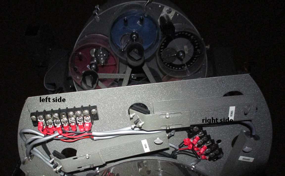
1c. Here is the underside of the cage, as normal orientation for the photographer. I will refer to the left side array of pins as the "Left side pins", and they are in stronger lighting here. I will refer to the shorter array of pins on the right side, and angled, as the "Right side pins" ... |
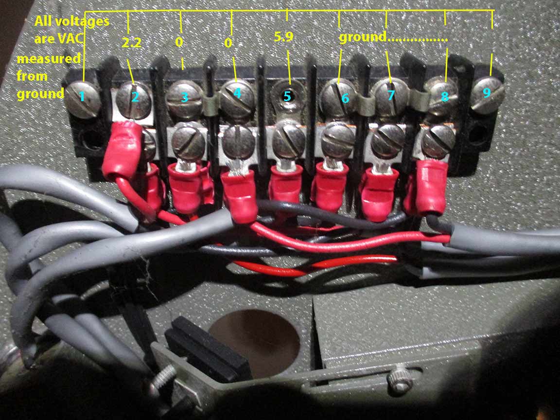
2c. Voltages were tested with my VOM. |
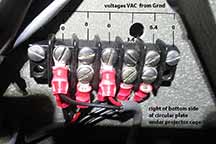
3c. This is the array of pins on the right side of the projector cage plate. Here were the voltages relative to the left side ground? pin, as shown, for the panel of pins on the right side of the cage plate. For "ground" I used the same 3-pin ground on the left side "barrier strip" as ground. |
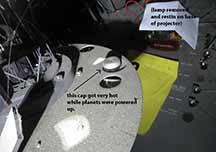
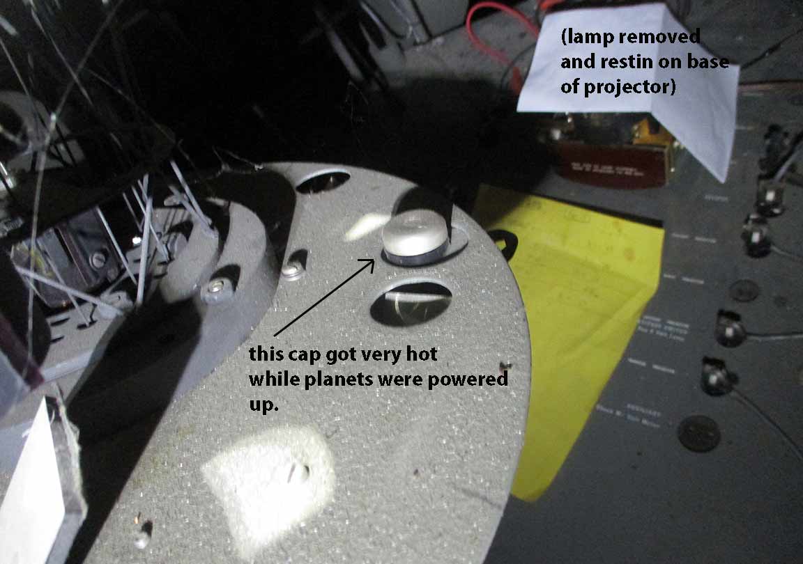
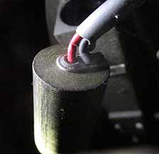
4c. The aluminum cap shown, was quite hot, almost too hot to touch, when powered as I described above. Eric says this is the cap for the sun lamp and it is normal for it to get hot after a few minutes. |
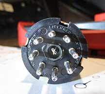
5c. For reference, here is the pin set sent to me by Eric at Ash. |
July 10, 2022 images from testing session. For the voltage and light tests, the following controls were turned on to maximum power:
* Stars, Sun, Moon, Inferior Planets, Superior planets.
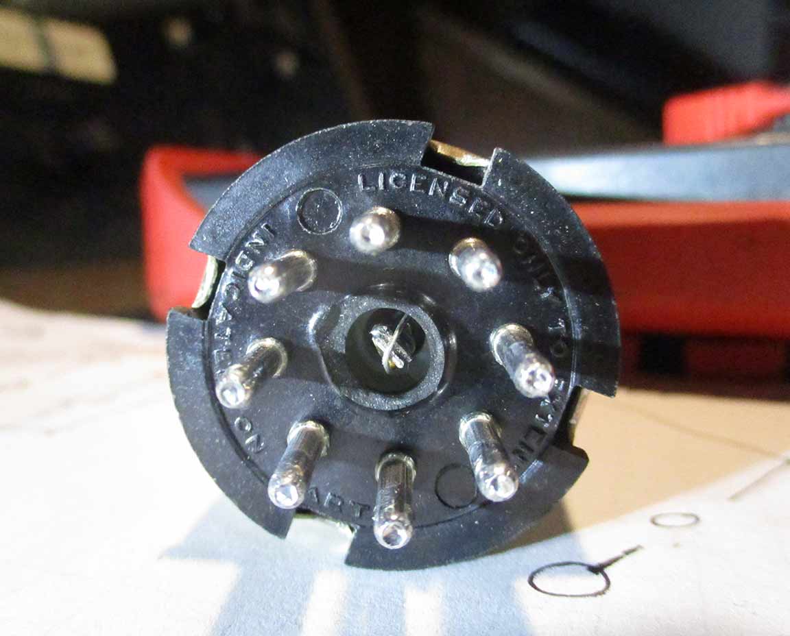
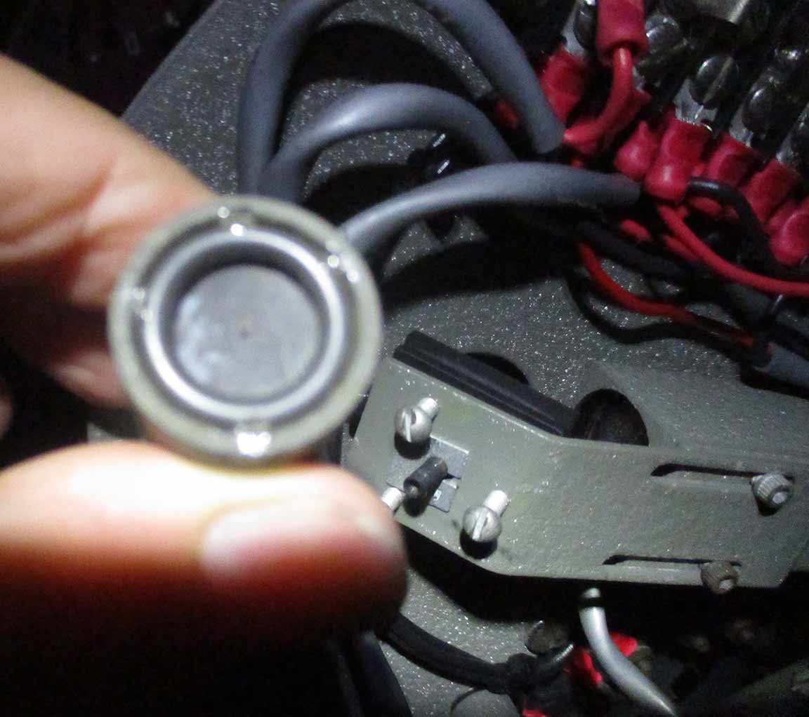
One of the "Gold Cans", bottom view |
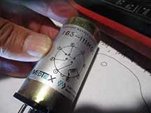
Gold can, side view |
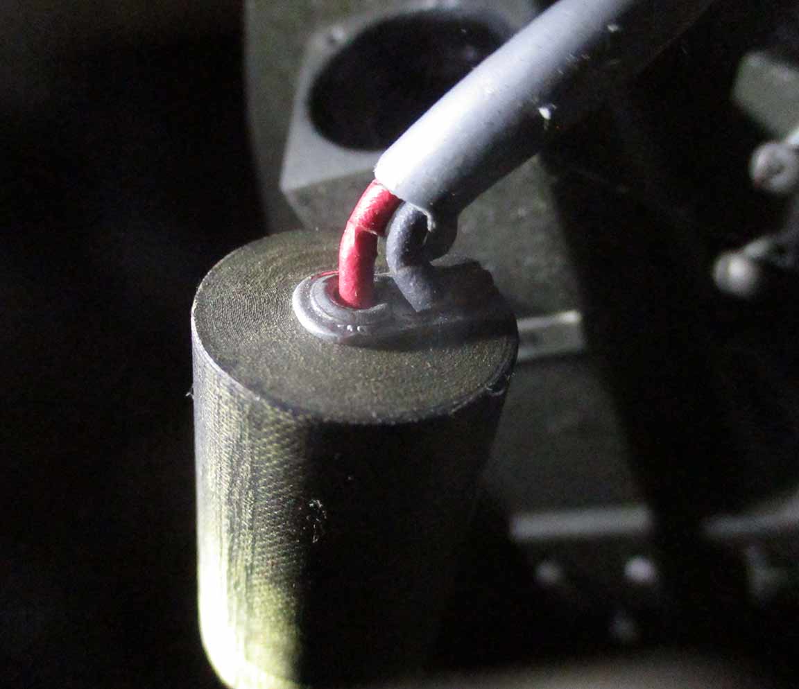
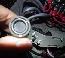
Gold can, socket |
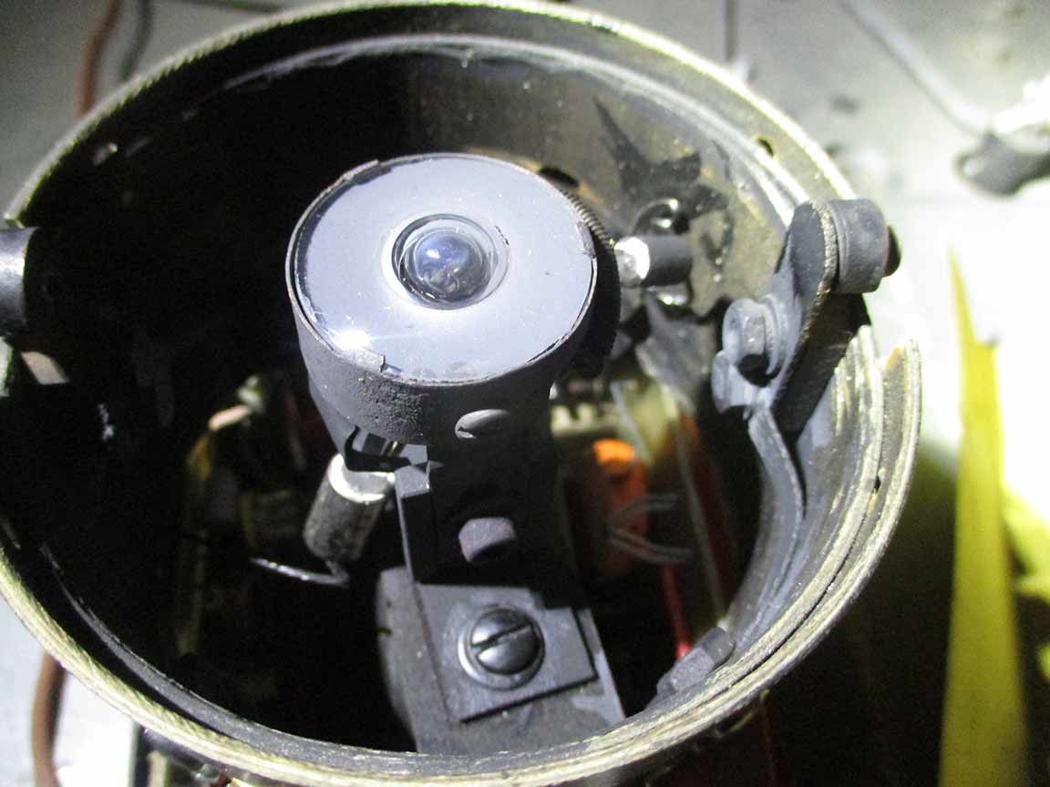
Projector lamp for Saturn, which was not lit. soldering looks good. |
Light source apparently emerges as a tight beam from that tiny hole. No light emerges. |
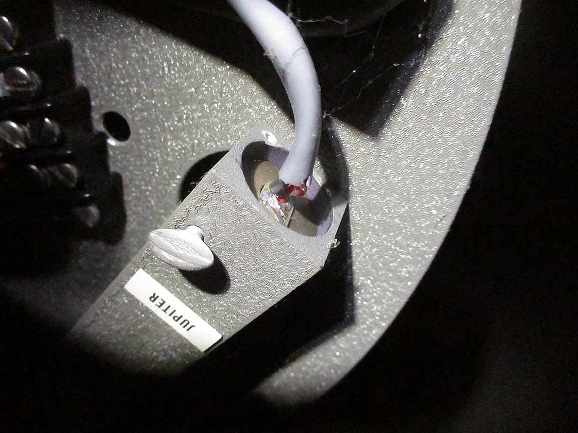
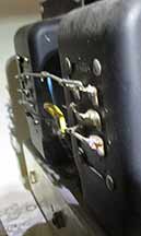
Jupiter light source. Soldering again looks good. |
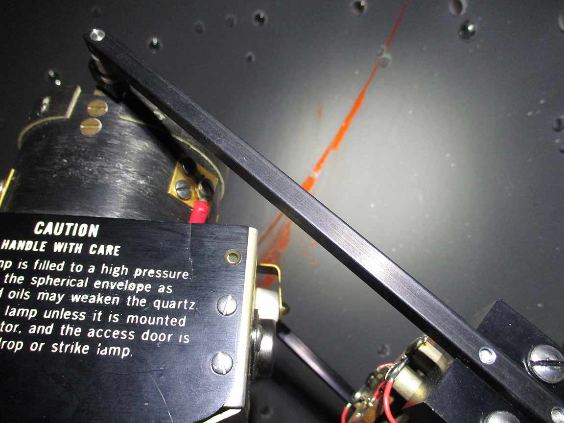
Rod which transmits from motor to the ball to do daily motion. It works smoothly, but it squeaks rather loudly. It was left on for days(?) apparently by janitor(s) or someone who took their midnight lunch break in the planetarium?? Don't know, but the daily motion was on when I next came to check the planetarium, early this summer. |
Pre-1986, the planetarium person made or installed this control box which sends power to various plugs in the sound, Kodak, and special effects around the projector. I insured these were all in the "on" position, but more testing could be done here as well. |
|
|
Next Testing Session Jobs:
* Swap the gold cans, CAREFULLY, on the bottom shelf box and see how/of the orange glowing lights on "Annual Motion" change. But - how to insure they get seated in the proper rotation??
* Wait for more instructions from Eric, and prepare to have Tom come down to do some testing, or perhaps receive the unit with the power transitor on the big heat sink to see if it's failed again.